5G and Autonomous Vehicles: The Road Ahead for Connectivity Testing and Compliance (Part 2)
In the previous post exploring the standardisation of technology for vehicle connectivity, we have seen that the existing connectivity technologies, such as C-V2X and U-V2X, do not have the capacity nor speed to reach the low-latency and data-rich connectivity required for level 5[1] autonomous vehicles.
The arrival of 5G technology will signal the key turning point towards fully connected vehicles. In this post, we explore the testing and compliance challenges for 5G connectivity.
5G’s key elements: Higher frequencies, beamforming and tracking
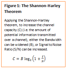
To increase the amount of data transmitted over a channel, engineers have three options: widen bandwidth, increase signal power or reduce noise (Figure 1). However, signal power is limited by regulation, and noise handling is restricted by technological limitations and the proliferation of radio-frequency (RF) devices in the environment.
To address the problem of data throughput and low latency, 5G essentially offers the solution by using higher frequencies to provide more bandwidth. However, moving up the radio spectrum leads to smaller wavelengths (cm or even mm), which fade away faster over distance. To offset this, 5G technologies use arrays of tiny antennae to dynamically track and concentrate their energy to send powerful beams in a single or given direction. Working at higher frequencies, with such dynamic antenna arrays, will require a completely new approach to test a device’s regulatory compliance.
Test challenge 1: Tiny high-frequency antennae disqualify conducted measurements
As the radio spectrum is a limited resource, radio equipment compliance requires an effective use of the spectrum to ensure coexistence between different radio services and reliability (such as signal quality, modulation bandwidth transmitted power, data throughput, etc.).
Historically, most compliance tests for radio equipment could be determined with a single set of conducted measurements, using coaxial cables to connect the test equipment directly to the device, without the antenna. Radiated measurements were only necessary for devices with integrated antenna characteristics.
The antennae required to beam high-frequency 5G signals (1cm or less wavelengths) are so numerous and compact that they need to be integrated, leaving no connectors available for conducted test methods. In addition, the measurements applied in one antenna are not the same as the sum of the total antennae because of beamforming. Therefore, laboratories cannot use radio-frequency conducted tests for compliance. The next generation of high-frequency 5G devices can only be tested over-the-air (OTA) with radiated-emission tests.
Test challenge 2: The Black Box vs White Box approach for OTA testing at high frequencies
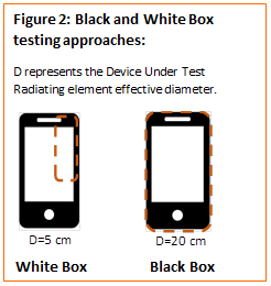
Over-the-air testing can be performed using two approaches: white box or black box tests (see figure 2). With the black box approach, no prior information about the antenna or radiating element’s location is required. Therefore, for testing purposes, the full volume within the enclosure is considered a radiating element. With the white box approach, the test is set up knowing the exact location of the antenna within the device.
At low frequencies, both white box and black box tests usually produce similar results because the position of the antenna and the shape of the device is not critical. Until now, the black box approach has been used for compliance purposes.
However, for the next generation of high-frequency 5G antennae arrays, knowing the positioning of the antennae is key to reduce measurement uncertainties associated with high frequencies. Additionally, a smaller device under test (see figure 2) also helps to reduce the measurement distance in far field conditions, as outlined later in challenge 6. This issue is still in discussion within technical committees, but the white box approach seems to be the most appropriate method.
Test Challenge 3: Dynamic antennae using multi-beams and beamtracking
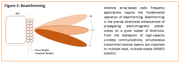
From a regulatory perspective, the testing challenges are driven by the need to test in dynamic, in-use behaviour, which is essential to ensure the device remains compliant. The question of how fast the beam can update its position to modify its angular focal point and beam quality therefore becomes essential, and this issue needs to be addressed by regulators (See figure 3).
Test Challenge 4: Testing transmitted-power in a 3-dimensional space
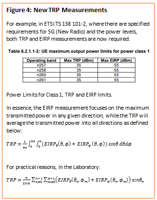
With current technology, Effective Isotropic Radiated Power (EIRP) measurements, which focus on the maximum transmitted power in any given direction, are sufficient for compliance testing. However, for 5G, regulators are pursuing a new testing methodology to combine classical EIRP tests with new Total Radiated Power (TRP) tests, which measures the average transmitted power from all directions.
In theory, TPR requires infinite measurements to capture all 3D directions; however, for practical reasons laboratories complete sampling tests (Figure 4). Although technically effective, TRP measurements are time consuming and require thousands of tests. For example, a manual EIRP measurement for a 4G mobile phone requires only one measurement. However, to measure TRP with resolution of 0.5º within a 3-dimensional space, the procedure would require 259,200 measurements. Even with fully automated state-of-the-art equipment, this will take several days for a single test case.
To overcome this restraint and reduce testing times, advanced beam-searching engines are being developed to perform the measurement in the relevant spatial coordinates, with a calculation extrapolated from the data. In fact, our engineers at Applus+ are working with technical committees to help define this future regulation, providing inputs from R&D tests completed at our laboratories.
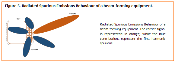
Test Challenge 5: Testing unwanted, spurious emissions in 3-dimensional space
Another test required is the Radiated Spurious Emissions test case. This tests the unintentional radiation outside the frequency band of the intended signal, and the test will need to take into account the beamforming of the device. Compliance testing will require analysis of the magnitude of spurious contributions from all the possible directions. Clearly, this will also impact on the complexity and duration of test campaigns.
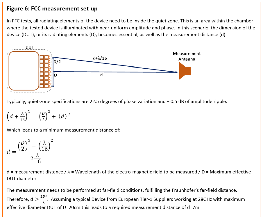
Test challenge 6: Test set-ups to meet the Far field condition requirement – measurement distance, sample size and measurement frequency
The strength of radiated fields attenuates over distance, particularly with high frequency emissions being more susceptible to attenuation affects. To deliver accurate results, over-the-air (OTA) testing must be performed at a certain distance known as the far field condition.
The far field distance depends directly on two concepts: the sample size and the measurement frequency. Increasing the size, or the operational frequency of the device, will lead to longer test distances. With this approach, a typical 20cm telecommunications control unit (TCU) operating at high frequencies will require a large testing distance (see figure 6). This is a long distance and such tests would require large, size semi-anechoic chambers, as used to test a complete vehicle. However, these chambers are only available in specialised test labs and R&D centres.
Direct Far Field (DFF) measurements, as outlined above, are historically the standard method to test over-the-air. However, the distances required to achieve this far field condition for high-frequency devices become impractical and require a lot of calibration time to compensate for the loss of signal.
Complementary to this Direct Far Field procedure, standardisation bodies, such as 3GPP, are also considering Indirect Far Field (IFF) to reduce the testing distances. These consist of creating a plane-wave field with a reflector in much less space than the DFF. In addition, Near Field to Far-Field (NFTF) is also being trialled, which relies on mathematical transformation to estimate the far field by measurements performed on a near field region (Figure 7).
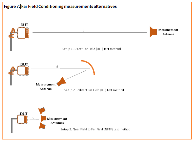
However, uncertainties are closely related to test setup. To provide accurate results, it is essential to control the uncertainty intervals related to these alternative test methods. This will be required to provide confidence in the results, otherwise any test effort and the results may be questionable.
Summary
5G will be the driving-force towards fully autonomous vehicles. At Applus+ Laboratories, our engineers have been exploring these fundamental changes in connectivity technology. Our team are collaborating in the design of the next generation of methodologies to test for the forthcoming regulatory compliance for connectivity technology.
For 5G components to delivery data-rich connectivity, high frequencies and dynamic beaming antennae are being developed. The nature of these two key elements will dramatically change the testing methodology, including new test cases, longer test sessions and advanced test equipment.
Testing laboratories, both independent and in-house, will have to adapt and be prepared for this revolution in testing methodologies. 5G technology will require new expertise, new test facilities and equipment.
In the next article, we will compare the results obtainable depending on the different types of test facilities utilised, examining a case study for over-the-air testing on a complete vehicle.
[1] SAE International/3GPP six-level classification system: level 0: No Automation to level 5: Full Automation. The automotive sector is currently at level 1 for state-of-art, high-end production vehicles (piloting level 3)
Written by Adrià Galín